Assemble a Pocket or DMG-01 Bivert Module
Technical wiki guide for assembling a Pocket or DMG-01 bivert module for Nintendo Game Boy LCD modifications.
A small no-wire bivert module
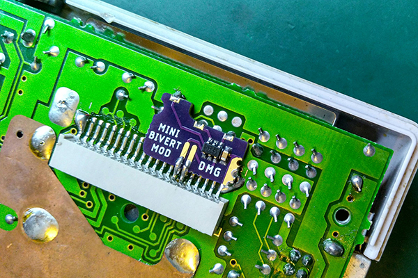
A bivert mod inverts the LCD drive signals used by the original Game Boy display path. It is commonly paired with LCD/backlight work to improve contrast and readability on modified consoles. This module packages the required inverter circuit into a very small PCB that solders directly to the Game Boy board.
The design goal is a cleaner installation: the module is shaped for the target console PCB and avoids the long point-to-point wires normally used in a hand-built bivert mod. The DMG and Pocket versions are different physical modules, so use the correct board for the console model.
This is a fine-pitch soldering mod. Work under magnification, use flux, avoid excessive heat on the LCD driver area, and verify the module orientation before soldering.
DMG-01 and Pocket use different boards
The Mini Bivert project has two practical installation families: the DMG version for the original Game Boy and the Pocket version for the smaller Game Boy Pocket PCB. The modules are designed to fit the corresponding board layout without extra wiring.
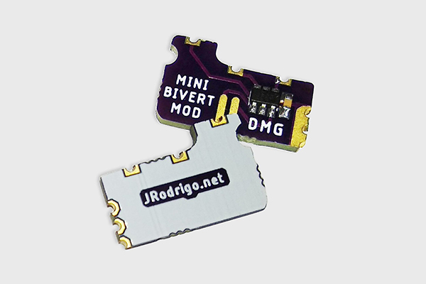
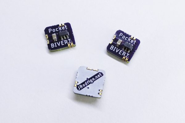
Mini Bivert for DMG-01
Designed for the original Nintendo Game Boy DMG-01 board. The module solders directly in the LCD driver area and provides the inverter circuit in a compact PCB footprint.
Pocket Bivert for MGB-001
Designed for the Game Boy Pocket board layout. The Pocket module uses its own shape and routing so it can sit correctly on the smaller PCB.
Minimal inverter circuit
The module is intentionally simple: a small PCB, a dual inverter gate and a decoupling capacitor. Keeping the circuit compact is what makes the installation cleaner than a fully hand-wired bivert mod.
Open the console and locate the install area
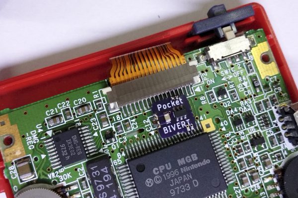
Disassemble the console enough to access the main PCB and LCD signal area. The module should be placed on the target pads/pins for the specific console version. Before soldering, dry-fit the board and check that the module shape, pin alignment and component side match the target area.
Do not assume the DMG and Pocket modules are interchangeable. The board outline and routing are different because the console PCBs are different.
Solder the module directly to the PCB
The key assembly detail is controlled alignment. The module is intended to remove the need for loose wires, but it only works cleanly if it sits flat and each solder joint connects to the intended pin or pad.
Clean and inspect the target area
Remove residue from the PCB, inspect the LCD driver pins/pads and verify there is no corrosion or previous solder damage.
Pre-tin lightly
Add a very small amount of solder to the target points and the module pads if needed. Too much solder will make alignment harder and can create bridges.
Align the module
Place the module in its final position and tack one point first. Re-check alignment before soldering the rest.
Solder the remaining joints
Use flux and short contact time. The goal is clean wetting on each pad without moving the module or overheating the surrounding area.
Clean flux and inspect under magnification
Check every joint, confirm there are no solder bridges and verify that the module has not lifted from the board.
Inspect before powering the console
A bivert module is small, but it sits in a critical display path. Most issues after installation come from orientation, solder bridges, cold joints or damaged pads.
Confirm the module variant and orientation before applying power.
Inspect adjacent pins/pads under magnification for solder bridges.
Use a multimeter to verify expected connections and no accidental shorts.
If the LCD is blank or distorted, power down and inspect all module joints again.
Re-check display contrast and related LCD/backlight work after the mod is installed.
Make sure the shell closes without pressing on the module or nearby components.
Project reference and source files
The Mini Bivert Module is open hardware and the repository contains the project README, images, license and BOM reference.